Quick Answer
Working Load Limit (WLL) = Minimum Breaking Strength (MBS) ÷ Safety Factor. For general lifting, use a safety factor of 5:1. For personnel lifting, use 10:1. Example: a 3mm 7x7 stainless steel wire rope with a minimum breaking strength of 6.79 kN (692 kgf / 1,527 lbs) has a WLL of 138 kgf (305 lbs / 1.36 kN) at a 5:1 safety factor. Use the interactive calculator below for any combination of construction, diameter, and safety factor.
Every wire rope failure investigation starts with the same question: what load was on the rope, and what load was it rated for? The gap between a rope's catalog breaking strength and the load it should actually carry in service is defined by two numbers — the Working Load Limit (WLL) and the safety factor — and misunderstanding either one is among the most common causes of rigging accidents.
This guide explains how WLL is calculated, which safety factor applies to which application, and how real-world conditions — sling angles, bending over sheaves, terminations, wear — reduce the capacity you can actually count on. It is written for engineers, riggers, and safety inspectors, but every calculation is worked through step by step so that a non-specialist buyer can follow along and specify the right rope with confidence.
What Is Working Load Limit (WLL)?
The Working Load Limit is the maximum load that may be applied to a wire rope in normal service, as specified by the manufacturer or the governing standard. It is derived directly from the rope's Minimum Breaking Strength (MBS) — also called minimum breaking force (MBF) or minimum breaking load (MBL) — using a single division:
WLL = Minimum Breaking Strength ÷ Safety Factor
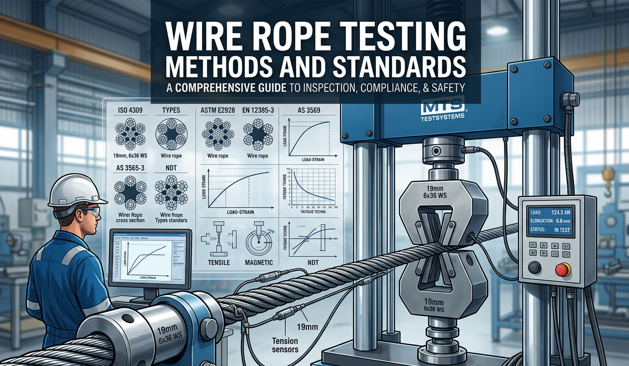
The MBS is the tensile force at which a new rope is guaranteed not to fail, verified by destructive testing of production samples — our guide to wire rope testing methods and standards explains exactly how those tests are run. The WLL, by contrast, is the number you design and operate to. A rope must never be loaded to its breaking strength, or anywhere near it: at loads approaching MBS there is zero margin for shock loading, dynamic effects, hidden wear, or estimation error, and permanent internal damage begins well before visible failure.
You will also encounter the older term Safe Working Load (SWL). WLL and SWL describe the same concept, but SWL has been phased out of most modern standards — the WLL vs SWL vs MBS section below explains the distinction in detail. What matters here is the hierarchy: MBS is a laboratory failure value; WLL is the working ceiling; your actual applied load should sit at or below the WLL.
Understanding Safety Factors
A safety factor (also called a design factor or factor of safety) is the ratio between the rope's minimum breaking strength and the maximum load permitted in service. A 5:1 safety factor means the rope must be at least five times stronger than the heaviest load it will ever carry.
Why so much margin? Because the published MBS describes a new, straight, dry rope pulled slowly in a laboratory — and nothing about field service matches those conditions. The safety factor absorbs:
- Dynamic and shock loads. Starting, stopping, and snatching a load can multiply the static force by 2x or more in a fraction of a second.
- Degradation over time. Abrasion, corrosion, and bending fatigue steadily reduce actual strength between inspections.
- Termination losses. Every end fitting — swage, clip, splice — transmits less than 100% of the rope's strength.
- Load estimation error. Field loads are rarely weighed; center-of-gravity shifts and unequal leg loading are routine.
- Consequence of failure. The more severe the outcome — especially any risk to people — the larger the required margin.
That last point is why safety factors are not one universal number. A guy wire that fails bends a pole; a man-riding hoist rope that fails kills someone. Standards bodies assign each application a factor proportional to its risk, which is what the next section maps out.
Safety Factor Table by Application
The table below summarizes the minimum safety factors used across common wire rope applications, followed by notes on each. Always confirm against the standard that governs your jurisdiction and industry — these are widely adopted minimums, not substitutes for your local code.
| Application | Minimum Safety Factor | WLL as % of MBS |
|---|---|---|
| General lifting & rigging | 5 : 1 | 20% |
| Personnel lifting / man-riding | 10 : 1 | 10% |
| Standing rigging (marine) | 3.5 : 1 | ~29% |
| Guard rails & barriers | 4 : 1 | 25% |
| Architectural / cable railing | 4 : 1 | 25% |
| Guy wires & stays | 3 : 1 | ~33% |
| Zip lines | 10 : 1 | 10% |
General Lifting & Rigging: 5:1
The 5:1 factor is the baseline for overhead lifting — crane hoist lines, cargo slings, and winch applications — established in ASME B30.9 for slings and echoed by OSHA and EN 13414. A sling rated to lift 1,000 kg must therefore be built from rope with at least 5,000 kgf of breaking strength. If your load sees frequent shock loading or the rope runs over multiple sheaves, many engineers step up to 6:1 or 7:1 voluntarily.
Personnel Lifting / Man-riding: 10:1
Whenever a rope carries people — suspended work platforms, man-riding baskets, rescue systems — the factor doubles to 10:1. OSHA 1926.1431 requires personnel platform suspension systems to have at least seven times the maximum intended load (ten times for non-rotation-resistant rope), and most international codes and site rules standardize on 10:1. There is no such thing as an acceptable failure when a person is on the hook.
Standing Rigging (Marine): 3.5:1
Yacht and small-vessel standing rigging — the 1x19 stays and shrouds that hold up a mast — is typically designed to about 3.5:1 against the maximum righting-moment load. The load is static and well-characterized, the rigging is inspected frequently, and weight aloft is a genuine performance penalty, so a lower factor is accepted. Grade 316 stainless is standard here for chloride resistance — see our guide to stainless steel wire rope in marine applications.
Guard Rails & Barriers: 4:1
Cable used as fall-protection infill on walkways, mezzanines, and machine guarding is normally designed to 4:1 against the code-specified design load (for example, the 200 lb / 0.89 kN concentrated load on a top rail in US practice). Because the load case is a short-duration push rather than a sustained lift, 4:1 provides an ample margin.
Architectural / Cable Railing: 4:1
Balustrade infill, green-wall trellis cables, and decorative tension members follow the same 4:1 logic as guard rails: static tension, predictable loads, easy inspection. Note that railing cables are pre-tensioned to 200–400 lbs each, and that pre-tension counts toward the working load. Our cable railing wire rope guide covers construction choice, diameters, and code requirements for these systems in detail.
Guy Wires & Stays: 3:1
Guy wires supporting poles, masts, and towers are designed to 3:1 in most utility and broadcast practice. The loads (wind plus pre-tension) are calculated by structural analysis rather than estimated, failure consequences are usually material rather than human, and the wires are individually inspectable — all of which justifies the lowest factor on this list.
Zip Lines: 10:1
Zip lines carry people, so despite being a "static" cable they are treated like man-riding systems: ACCT and ASTM F2959 practice works out to roughly 10:1 on the main cable against the maximum dynamic rider load. Remember that a taut zip line under a rider's weight sees far more tension than the rider weighs — a cable sagging only a few degrees multiplies the load several times, which is the same vector effect covered in the sling angle section below.
WLL Calculation: Step-by-Step
Every calculation follows the same three steps: find the MBS from the manufacturer's table, choose the safety factor for your application, and divide. The MBS values used below are from our complete wire rope breaking strength chart (GB/T 9944-2015, 1770 MPa grade).
Example 1 — 3mm 7x7 for general rigging (5:1)
- MBS of 3.0mm 7x7 stainless steel rope = 6.79 kN (692 kgf / 1,527 lbs).
- Application is general rigging → safety factor = 5:1.
- WLL = 6.79 kN ÷ 5 = 1.36 kN ≈ 138 kgf (305 lbs).
So a rope that breaks at nearly 700 kg may only carry about 138 kg in lifting service — one-fifth of its laboratory strength. This surprises many first-time buyers, but it is exactly the margin that keeps a shock-loaded, slightly worn rope from becoming a statistic.
Example 2 — 6mm 7x19 winch line (5:1)
- MBS of 6.0mm (1/4") 7x19 = 25.06 kN (2,555 kgf / 5,633 lbs).
- Safety factor for lifting = 5:1.
- WLL = 25.06 ÷ 5 = 5.01 kN ≈ 511 kgf (1,127 lbs).
Example 3 — 8mm 7x19 for a suspended platform (10:1)
- MBS of 8.0mm (5/16") 7x19 = 44.53 kN (4,541 kgf / 10,011 lbs).
- Personnel lifting → safety factor = 10:1.
- WLL = 44.53 ÷ 10 = 4.45 kN ≈ 454 kgf (1,001 lbs).
Example 4 — Working backwards from the load
In practice you usually know the load and need to find the rope. Suppose you must lift 500 kg (4.90 kN) in general service at 5:1. The required MBS is the load times the factor: 4.90 kN × 5 = 24.5 kN minimum. Scanning the 6.0mm row of the breaking strength chart: 7x19 offers 25.06 kN and 7x7 offers 27.15 kN — either works, so choose the construction by flexibility requirements (see our 7x7 vs 7x19 construction comparison). If the same load carried personnel at 10:1, the required MBS doubles to 49 kN, pushing you to 10.0mm 7x19 (69.59 kN) or 8.0mm 1x19 (64.63 kN).
Interactive WLL Calculator
Select a construction, diameter, and safety factor to calculate the Working Load Limit. WLL = Minimum Breaking Strength ÷ Safety Factor. Breaking strength values are minimum guaranteed figures per GB/T 9944-2015 (1770 MPa grade stainless steel).
Minimum Breaking Strength (MBS)
2,555 kgf
5,633 lbs · 25.06 kN
Working Load Limit (WLL) at 5:1
511 kgf
1,127 lbs · 5.01 kN
* For guidance only. WLL assumes a new, straight rope with 100% efficient terminations under static load. Apply additional derating for terminations, sling angles, bending, and wear — see the sections below. Always verify against the manufacturer's test certificate for critical or life-safety applications.
WLL vs SWL vs MBS: What's the Difference?
These three terms are the most frequently confused in wire rope specification, and mixing them up can be dangerous — a rope bought against its MBS carries five to ten times less than the buyer assumed.
| Term | What it means | Who defines it |
|---|---|---|
| MBS / MBF / MBL | Minimum force at which a new rope is guaranteed to break; verified by destructive test | Manufacturer, per ISO 2408 / EN 12385 / GB/T 9944 |
| WLL | Maximum load permitted in normal service; WLL = MBS ÷ safety factor | Manufacturer or standard, per application |
| SWL | Legacy term for the same working ceiling; superseded by WLL in modern standards | Historically the equipment owner or regulator |
Why SWL fell out of use: "Safe Working Load" implied a legal guarantee of safety that no manufacturer can honestly make, since actual safety depends on how the rope is used, inspected, and maintained. Standards bodies (led by ASME and ISO) replaced it with the more precise Working Load Limit. In older documents the two are interchangeable; in current practice, specify and mark equipment with WLL. One subtlety: a site engineer may still assign an application-specific "SWL" lower than the catalog WLL — for example derating for a known shock-load environment — but never higher.
Factors That Reduce WLL
The WLL from the formula assumes a new, straight rope, loaded in pure tension, with perfect end terminations. Field conditions chip away at that number, and the reductions multiply:
- Terminations. A machine-swaged fitting keeps 90–95% of rope strength; wire rope clips about 80%; a knot as little as 50%. The assembly is only as strong as its weakest termination.
- Bending over sheaves and around pins. Wrapping a rope around anything adds bending stress to the tension. The strength loss is governed by the D:d ratio, covered in the next section.
- Sling leg angle. Legs pulling at an angle carry more tension than the load weight divided by the number of legs — see the sling angle table below.
- Wear and corrosion. A 10% loss of metallic cross-section costs roughly 15% of breaking strength; pitting corrosion is worse because it seeds fatigue cracks. This is why WLL is only valid for a rope that passes inspection.
- Temperature. Stainless rope holds full strength to about 300°C; above that, capacity falls progressively (roughly 5–10% at 400°C, 20–30% at 500°C). Fibre-core ropes and aluminum ferrules have far lower limits than the wire itself.
- Shock loading. A load dropped even a short distance onto a slack rope can momentarily double or triple the force. If shock loading is routine, increase the safety factor rather than hoping the margin covers it.
A realistic capacity check chains these together. Take Example 2's 6mm 7x19 winch line (WLL 511 kgf at 5:1): rig it with wire rope clips (×0.80) and run it over an undersized pulley at D:d = 10 (×0.86), and the effective assembly strength drops to 25.06 × 0.80 × 0.86 ≈ 17.2 kN — the honest WLL at 5:1 is now about 351 kgf, not 511.
D:d Ratio and Bend Efficiency
Whenever a wire rope bends around a sheave, drum, or pin, the outer wires stretch more than the inner wires, adding bending stress on top of the working tension. The severity is captured by the D:d ratio — the diameter of the bend (D) divided by the diameter of the rope (d). A 60mm sheave with a 6mm rope gives D:d = 10. The smaller the ratio, the more strength the rope loses at the bend:
| D:d Ratio | Bend Efficiency (approx. strength retained) |
|---|---|
| 40 : 1 | 95% |
| 30 : 1 | 93% |
| 20 : 1 | 91% |
| 15 : 1 | 89% |
| 10 : 1 | 86% |
| 8 : 1 | 83% |
| 6 : 1 | 79% |
| 4 : 1 | 75% |
| 2 : 1 | 65% |
| 1 : 1 | 50% |
Two practical rules follow. First, keep sheaves generous: at least 20× rope diameter for 7x19 construction, 25× for 7x7, and 35× for rigid 1x19. Second, remember the 1:1 row — bending a rope around a pin its own diameter (or tying a knot, which is worse) cuts strength roughly in half. This is also why a sling choked around a small shackle pin has less capacity than the same sling in a straight pull. Bend efficiency losses are immediate; the long-term penalty of small D:d ratios is accelerated bending fatigue, which shows up as broken wires at the sheave tangent points during inspection.
Sling Angle Factor Table
When a load hangs from two or more sling legs, the legs are almost never vertical — and the moment they lean, the tension in each leg exceeds its share of the load. Picture two legs running from a single crane hook down to lifting points at either end of a crate: the wider the lifting points, the flatter the triangle, and the harder each leg must pull inward against the other to support the same vertical weight. The leg tension equals the leg's share of the load multiplied by 1 ÷ cos(θ), where θ is the leg's angle measured from vertical:
| Angle from Vertical (θ) | Capacity Factor (cos θ) | Tension Multiplier per Leg |
|---|---|---|
| 0° (vertical legs) | 1.000 | 1.00× |
| 15° | 0.966 | 1.04× |
| 30° | 0.866 | 1.15× |
| 45° | 0.707 | 1.41× |
| 60° | 0.500 | 2.00× |
Worked example: a 1,000 kg crate on two legs at 45° from vertical loads each leg to (1,000 ÷ 2) × 1.41 = 707 kgf — not 500 kgf. Each leg's WLL must therefore be at least 707 kgf. At 60° from vertical the multiplier reaches 2.0, meaning each of the two legs carries the entire load's weight; beyond 60° the tension grows so quickly that most standards and site rules prohibit rigging flatter than this. If your sling charts state angles from horizontalinstead, the same rows apply in reverse: 60° from horizontal equals 30° from vertical.
Inspection & Retirement Criteria
A WLL is a property of a rope in serviceable condition — the moment a rope fails inspection, its WLL is zero. Ropes in lifting service should get a documented inspection before each use and a thorough periodic examination by a competent person. Retire a wire rope immediately when you find any of the following (per ASME B30.9 and ISO 4309 practice):
- Broken wires: ten or more randomly distributed broken wires in one rope lay, or five in a single strand in one lay; any broken wire at a termination.
- Diameter reduction greater than about 7% of nominal, from wear or core failure.
- Kinks, birdcaging, crushing, or any other distortion of the rope structure.
- Significant corrosion — especially pitting — or any evidence of heat damage such as discoloration or welding splatter.
- Damaged or slipping end fittings: cracked swages, deformed thimbles, loose clips.
The full 12-point procedure, including how to measure diameter correctly and count broken wires per lay length, is in our wire rope inspection checklist. For architectural and standing-rigging cable that lives outdoors, add an annual close inspection of terminations, where crevice corrosion concentrates.
Relevant Standards
WLL and safety factor requirements come from an ecosystem of overlapping standards. The ones most often cited for stainless steel wire rope are:
- ISO 2408 — the international umbrella standard for steel wire ropes: constructions, minimum breaking force tables, and test methods.
- EN 12385 — the harmonized European standard family for steel wire ropes; Part 4 covers stranded ropes for general lifting.
- ASME B30.9 — the US sling standard defining the 5:1 design factor for wire rope slings, plus inspection and removal criteria.
- AS 1666 — the Australian standard for wire rope slings, aligned to the same 5:1 design factor and marking requirements.
- GB/T 9944 — the Chinese national standard for stainless steel wire rope; the source of the breaking strength values used throughout this guide.
- ISO 4309 — crane wire rope care, inspection, and discard criteria.
When two standards could apply, follow the stricter one — and remember that a purchase specification can always demand more than the minimum. For help matching grade, construction, and diameter to your standard, start with our guide on how to choose the right stainless steel wire rope.
Frequently Asked Questions
How do you calculate the working load limit of wire rope?
Divide the rope's minimum breaking strength by the safety factor for your application: WLL = MBS ÷ Safety Factor. For example, a 6mm 7x19 stainless steel rope with a 25.06 kN breaking strength has a WLL of 5.01 kN (about 511 kgf / 1,127 lbs) at the 5:1 factor used for general lifting.
What is the difference between WLL and SWL?
They describe the same working ceiling, but WLL (Working Load Limit) is the current standard term while SWL (Safe Working Load) is a legacy term phased out because it implied a guarantee of safety. Modern equipment is marked with WLL; if a site assigns its own SWL, it may be lower than the catalog WLL but never higher.
What safety factor should I use for lifting?
Use a minimum of 5:1 for general lifting and rigging (per ASME B30.9), and 10:1 whenever the rope carries people. Static applications use lower factors: 4:1 for guard rails and architectural cable, 3.5:1 for marine standing rigging, and 3:1 for guy wires.
Does sling angle affect the working load limit?
Yes. When sling legs lean away from vertical, each leg's tension is its share of the load multiplied by 1 ÷ cos(θ). At 45° from vertical the tension is 1.41× the leg's share; at 60° it is 2.0×. Rigging flatter than 60° from vertical is prohibited by most standards because tension rises steeply beyond that point.
What is the D:d ratio and why does it matter?
D:d is the bend diameter divided by the rope diameter. Bending a rope reduces its effective strength: at D:d = 20 the rope retains about 91% of its strength, at 10 about 86%, and around a pin its own diameter (1:1) only about 50%. Keep sheaves at least 20x rope diameter for 7x19, 25x for 7x7, and 35x for 1x19 construction.
When should a wire rope be removed from service?
Retire a rope when you find ten or more broken wires in one lay (or five in one strand), diameter reduction over about 7%, kinks or crushing, significant corrosion or heat damage, or any damaged end fitting. A rope that fails inspection has no working load limit — replace it before the next lift.
Get the Data Behind the Calculation
Every WLL starts from an accurate breaking strength. Our complete wire rope breaking strength chart lists minimum breaking force for 1x19, 7x7, and 7x19 stainless steel constructions from 0.5mm to 16mm, in both metric and imperial units — the same GB/T 9944-2015 data used by the calculator above.
Specifying rope for a lifting system, a personnel application, or anything safety-critical? Our engineering team can confirm the right construction, diameter, and grade for your required WLL and supply break-test certificates with every production lot. Contact us for technical support — we typically respond within 2 hours during business hours.